I decided to convert my original Cybots to run on 3.7v rechargeable batteries.
Demonstration of my Cybot running on rechargeable Li-Po batteries.
Components:
4 Number 3.7 volt Li-Po batteries, I'm using 1200mAh. (Other sizes will be
OK)
4 Number connectors with leads that fit the battery connectors.
2 Number Bucks, I'm using
MH-MINI-360 DC-DC Buck
This modification is for Cybots that have the power upgrade from issues 53 and
54.
I also recommend it has the power regulator fix that was issued with issue
59;
If the Cybot has the newer Power Board then this fix is not needed.
First Power Board, without 7808 Regulator.
Second Power Board with 7808 Regulator
The first thing to do is make the Adaptor Cable:
Trim the wires on the battery connectors and join as follows.
Next trim the remaining wires and solder them to the Bucks as shown.
Next add cables to the other side of the Buck.
Next Join the two Bucks in the following way.
The next thing to do, is get the plug from the 8xAA Battery Box:
First remove Batteries and the four screws holding the front panels of Cybot.
Carefully lift the front panels, and remove the battery plug, the two screws
holding the power board, and the four screws holding the 8xAA Battery Box.
Now remove the 8xAA Battery box and cut the plug from it with about 30mm wire.
Now solder the plug to the two Bucks.
Now the voltage needs setting on each Buck.
Each Buck needs to be set individually.
Connect four fully charged batteries to each of the sockets.
Using the adjustment potentiometer, carefully set the First Buck to 6 Volts.
Using the adjustment potentiometer, carefully set the Second Buck to 6 Volts.
After setting both Bucks to 6 volt. Connecting the Volt Meter to Red and Black
should read 12 Volt.
Now that the Voltage is set, insulate the Bucks with tape.
(Leave the ends open so air can flow through)
Now the new battery lead is complete, disconnect the batteries from the lead
and connect it to the Power Board inside Cybot.
I held the Power Board in place, against the other boards, with a hair band.
(any sort of elastic band or Nylon Plastic Cable Ties will do)
After securing the Power Board in place, refit the front panels of Cybot.
Then the batteries can be re-connected to the new cable. (Batteries can be
held together with a band or tie)
Place the batteries inside Cybot.
Fit the Battery Lid.
All done, ready to rumble.
NOTE! The Bucks are fitted to the batteries before the switch on the Cybot. Un-Plug the Batteries from the Bucks when not in use. The Bucks will drain the batteries even if the Cybot is switched off. (If LiPo Batteries are drained below 3 volt, they may be rendered
useless).
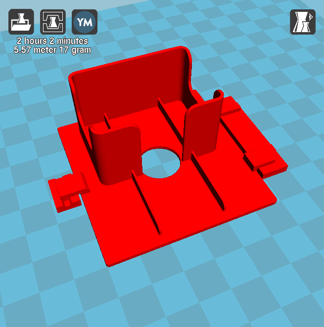
I decided to make some 3D Printed parts to hold the Power Board and the
Batteries in place.
This project is to create an Infrared Remote Control to control the Original
Cybot received with the magazine Ultimate Real Robots, started back in
2001
At the moment it transmits the required codes to:
SONAR: -AVOID FAST. Avoids objects at fast speed. -AVOID SLOW. Avoids objects at slow speed. -FOLLOW. Follows objects. LIGHT: -FOLLOW FAST. Follows light as fast speed. -FOLLOW SLOW. Follows light as slow speed. -AVOID FAST. Avoids light as fast speed. -AVOID SLOW. Avoids light as slow speed. LINE FOLLOW. Sets it in line follow mode. REMOTE MODE. Using the 4 buttons, can control the direction of the
motors.
Also there is the menu to set the channel.
I have tried to keep the menu system the same as the original Cybot
Handset.
Reason for making the remote:(a little history)
Before the issue of the parts for the IR handset, Cybot was put into different
modes by selecting DIP Switches. (There was no issue with Cybot while this was
the case)
When the IR Handset was issued, things changed. A processor was upgraded to
change the function of the DIP Switches. The DIP Switches where then used to
set the channel used by the IR Handset so that more than one Cybot could be
used together at the same time. (Up to 16 Cybot could be controlled with the
Infrared Controls )
However, when the Infrared-Download-Board was issued, there where problems.
Not all the boards where manufactured the same, there where issues that made
some not work correctly or not work at all. There was a fix issued but this
did not fix all.
I was one of the unlucky ones, nothing worked for me from there on, everything
relied on the Infrared Handset working.
If you, like me, was one of the unlucky ones that had the same problem, you
may wish to dig out your old box of Cybot bits and make this Infrared
Controller to control it.
Lets Start.
First the prototype.
Before making the handset I built a prototype to test thing out and make sure
my code worked.
Breadboard View
The Circuit
R8 and R9 are pullup resistors for the I2C bus. a lot of people forget to add
these to the circuit, but they are required. (one pair per bus, not device)
As a rule of thumb to the resistors are added to the master, but as the
Arduino could be used as master or slave and to keep things simple, internal
pull are not used in the library.
I have used Internal Pullup Resistors for the Pins connected to the switches.
So all Switches are to close to Ground.
The Resistor / Capacitor Pairs R1 to R7, C1 to C7 are to compensate for
bounce. (so are not necessary if you want to do a quick test, I recommend them
for stability)
Q1 is the driver for the Infrared LED (940nm). This is so full power is used
by the LED to transmit the signals. (again if testing next to your Cybot, Q1,
C8 and R11 can be removed. Connecting R10 and LED1 in series between Pin D3
and 5v should work)
For the Built version I use External Pullup Resistors.
Arrduino NANO:
Tims_Cybot_Transmitter_Nano_Atmaga328P.hex
Using External Pullup Resistors.
Arduino UNO:
Tims_Cybot_Transmitter_Genuino_Uno.hex
Using External Pullup Resistors.
(I don't know if HEX Files have the bootloader in them, but I did these HEX
Files with it configured to Old Bootloader for the NANO)
XLoader is an easy program to use, you don't need to install it, it is a
standalone program that runs from wherever yo put it. You tell it where the
file is and tell it where to send it.(the port your NANO is plugged into)
As the Arduino NANO does not have a Voice/Sound processor It will not be able
to do those related commands.
Next step is to make a functional usable Handset.
Rather than make one circuit board and mount everything to the one board, I
have decided to make this project modular.
By making it modular, some modules may be found on the internet.
List of Components / Modules:
Arduino NANO
The chip needs to be ATmega328 (If you are using China Clones)
This program uses 90% of both SRAM and EEPROM
OLED
Mono (Black and White)
0.96 inch
128 x 64 pixels
I2C connection
Rotary Switch with Push Button
I made this board my self.
I wanted external pullup resistors and de-bounce on all switches.
Some rotary switch modules can be found on the internet.(be sure they have
pullup resistors on the board)
It can be made on a Perfboard.
Here is a
Fritzing file:
Tims_Rotary_Switch.zip
(Obviously the wires go under the board)
Infrared Transmitter
I made this board my self.
There are some modules on the internet, but be sure to get one that has a
driver. (has a transistor to power the IR LED from the power supply)
It can be made on a Perfboard.
Here is a
Fritzing file:
Tims_Infrared_Transmitter.zip
(Obviously the wires go under the board)
Control Buttons
Luckily I had a 4 button panel I removed from an old Epson printer.
This panel has pullup resistors and de-bounce components fitted to it.
But not every one has a box full of old bits to use, so here is the
circuit.
It can be made on a Perfboard.
Here is a
Fritzing file:
4_buttons_with_Debounce_and_Pullup.zip
(Obviously the wires go under the board Apart from one)
A Note on making it on a Perf-Board, the top and bottom fits into plastic
parts I made on my 3D Printer.
The size of the board should be 65mm X 40mm.
When fitting the plug to the cable, note that the pins are as follows:
Left Forward = pin D7
Left Reverse = pin D8
Right Forward = pin D6
Right Reverse = pin D9
Power and I2C Bus-Board
To make things easy to connect all the components together I have made a
Bus-Board for the power and I2C.
Putting the I2C bus on the board with the power makes it easy to add the 2
Pullup Resistors required for the I2C Bus.
(As I have only one I2C component, I only needed to fit 2 headers on that
bus)
It can be made on a Stripboard.
Here is a
Fritzing file:
I2C_Bus.zip
To connect all the components together a few cables need making.
The first parts to fit are:
The Switch to the Switch Side. (2 x small screws)
Infrared Transmitter Module to the Base. (2 x M3x10 flat end self tappers)
Power and I2C Bus-Board to the Base. (2 x M3x10 flat end self tappers)
Rotary Switch Module to the Base. (M7 Nut)
Place Battery with Battery Clip on Base.
Fit Switch Side to Base over the Battery Clip. (2 x M3x10 flat end self
tappers)
Fit cables from the Switch to the Battery and the Arduino NANO.
The Cable to the Arduino NANO goes to the pins VIN and GND.
How the Assembly should look so far:
Before fitting the Arduino NANO to the base, it is a good time to fit some of
the cables to the Arduino.
See picture above for cable lengths and ends.
Arduino to Power-Bus. The split connector end goes to pins 5V and
opposite GND. Arduino to I2C Bus. Connect to pins A4 and A5. Arduino to Encoder Buttons. Connect to pins A0, A1 and A2. Arduino to IR. Connect to pin D3.
How the Assembly should look so far:
Now the Arduino can be fitted in place. (lower cables need to be bent up )
Then: Arduino to Power-Bus. Connect to pins on the Bus-Board, 5V to VCC, GND
to GND. Arduino to I2C Bus. Connect to pins on the Bus-Board, A4 to SDA, A5 to
SCL. Arduino to Encoder Buttons. Connect to Encoder Module. Arduino to IR. Connect to Infrared Module.
Connect Power Bus to IR.
Connect Power Bus to Encoder Module.
Connect Power Bus to OLED. (just to the power bus at the moment)
Connect I2C Bus to OLED. (just to the I2C bus at the moment)
How the Assembly should look so far:
Next is to fit the NANO Side.
This has 2 NANO Clips attached (1 x M3x10 flat end self tapper in each)
Next is to fit the Button Board Supports to the Button Board.
Next is to connect the Button Board and the OLED
The cables for the Button Board go through the NANO Side Support.
Power Cable goes to the Power Bus.
The Button Cable connects as follows:
Left Forward = pin D7
Left Reverse = pin D8
Right Forward = pin D6
Right Reverse = pin D9
The OLED connects to the previously connected cables to the Bus Board.
Now the Button board and OLED Support can be fitted to the top. Also the Knob
for the Rotary Encoder.
Finally fit the OLED to it's support. (2 x M2 self tapping screws)