Tuesday 15 February 2022

Control Cybot from Web Browser using ESP32-CAM

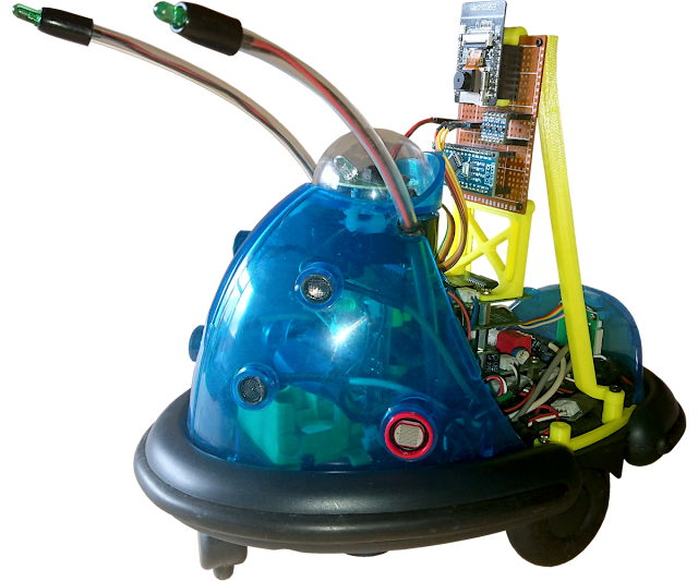
I wanted to give Cybot Sight, that is add a camera to Cybot.


To do this, I decided to use an ESP32-CAM module.

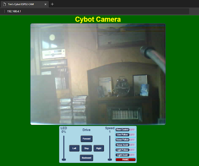
Using an ESP32-CAM module will also enable me to control Cybot from a web browser.
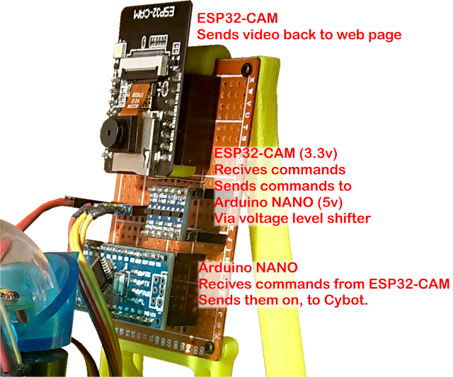
To control Cybot with the ESP32-CAM module requires tapping into the Two-Wire Communication Bus.
The Two-Wire protocol used by Cybot is very similar to the I2C standard, but not quite the same.
So to use a modified I2C protocol to talk to Cybot, I need to use an Arduino NANO to translate the ESP32-CAM I2C protocol commands to the Cybot I2C protocol commands.


This means that all the original hardware on Cybot can be used and controlled from a web browser.


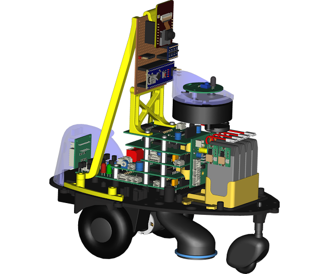
To mount all the components for the Camera Board, I used a cheap PY-5CM*7CM perforated board.


As the ESP32-CAM is 3.3v and the Arduino NANO and Cybot are 5v.
A logic level shifter is also needed.

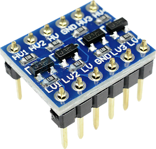
The ESP32-CAM has a 5v input, this goes to a 3.3v voltage regulator, which can handle more than 5v input. This input is connected to the 6v side of the battery supply of Cybot under the new power board.
The 6v side of the power supply is for the motors, but by the time it gets to the motors its about 4v.
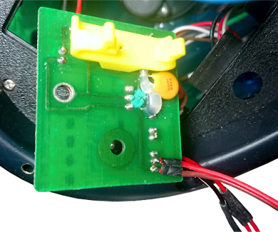
So I have connected the ESP32-CAM here before any voltage drop at the battery supply because the camera and Wi-Fi draws quite a bit of power. If the power drops it can create a brownout.

The power for the Arduino NANO is taken from the header that stacks through all the circuit boards.
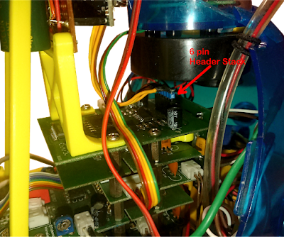
The pins on the header are:
  1. Ground.
  2. 6 volt supply. (I haven't used this due to voltage drop)
  3. 5 volt supply.
  4. SCL. Two-Wire Clock.
  5. SDA. Two-Wire Data.
  6. Reset for Drive Microcontroller.
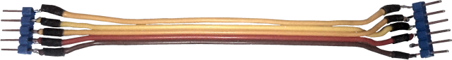
Made a cable to go from headers to the Camera Board.

I have done a Fitzing of the Camera Board circuit.


The Male Header for the power to the ESP32-CAM is separate from the cables to the Cybot, so that it can be disconnected from the batteries.

Designed some support and printed them on my 3D printer.
These are the STL files:
Those that end with R in there name require a mirror image making to make a left version.


I have done code for the ESP32-CAM and Arduino NANO.
They are all in this file: Pub_Cybot_ESP32CAM_Control.zip
There are three versions of HEX file for the NANO, no bootloader, old bootloader and new bootloader.
I have added XLoader to install your choice.


Sunday 19 April 2020

Those stupid plastic Tabs


I have been asked to share what I did with the plastic tabs that hold the dome.

The original tabs are not the best design for this fixing, I have found with the blue transparent front halves of Cybot, these get broken off.

If they haven't snapped of completely yet, I reinforced them with plastic parts and epoxy glue.
(rough up the area where glue it to be)
There was two types I made, one for those still in one piece and one for those that have the tip where the screw goes broken. (the printed pieces may need trimming to fit good)
STL Files:

For those that have broken off completely.
I made a bracket that I screwed in place to support the dome.

This is made out of two parts screwed together.
STL Files:


Drilled some holes for the screws.

There are some other 3D printed parts I have made to improve things.


The rubber "O" ring around the bottom of the Line Sensor has probably perished by now.
I made a plastic one.
You will also see a plastic part I have fitted to the motors.
This piece lines up the motors (motor gear) more accurately.
It reduces the noise that comes from the gearbox.

 
STL Files:


Also there are the LED mounts.
If you don't want the long antenna, I made these.

Print, one as is and one mirrored.

STL File:

Another item was the front wheel, this was supposed to be easily removable so that it could be swopped out for the Cyball attachment.
The tabs on one of mine broke during this process.
I decided to make anew one for the Cybot I converted to Arduino.

While drawing Cybot I discovered that the front wheel was a little long in the stem.
It raises the front of Cybot, I don't know if it was done on purpose. 
This is probably why Cybot dose not like to go in a straight line.
I have decided to make my new one so that Cybot sits level.

Some items will need purchasing for this:

1 x M3x10mm self tapping screw.
1 x M3x25mm set screw.
2 x 3mm(hole)x10mm(OD)x4mm(width) roller bearings.

The original wheel and spindle


STL Files:

A cut through section to show how it goes together.


Saturday 9 November 2019

Converting Tom to run on three 3.7 volt rechargeable Li-Po batteries


Decided to convert Tom, as I did Cybot.
Big improvement to the working of Tom adding Li-Po Rechargeable Batteries.
Video showing improved performance from Tom.

Parts Needed:

3D Printed:

New Lower Tail Rib with Battery Holder
STL File: Lower_Tail Rib_with_Battery_Box.stl

Purchased:

3 No. Li-Po Batteries, I am using 1200mAh.
3 No. Connectors that connect to the Batteries. (with leads)
1 No. mini 360 Buck. (DC-DC Drop down voltage regulator, to 9 volt)
1 No. matching Pair (1 x plug and 1 x socket) to connect to Tom. (with leads)
1 No. plug that matches the pair for Tom. (with leads)

The First Step is to add new Power Leads to Tom.

First remove the Top Casing off of Tom.
And remove the Power Plug from the Power Board.
The two screws that hold the Power Board in place will need to be removed, so that the Power board can be lifted slightly, to enable this to be done.

Next, cut the cables about 15mm from Power Plug.
WARNING! Cut one at a time if you have not removed the batteries.
Next, take a matching plug and socket.
The Plug is going to be connected to the wires still attached to Tom.
The Socket is going to be connected to the wires on the plug cut away from Tom.
Connect Red to Red and Black to Black.
It is important which is fitted.

Now fit the cable with Tom's Power Plug back into the Power Board.
Push the Power Board back in correct position and fit the power Boards two retaining screws.
Re-Fit the Top Casing of Tom with the cables passing through hole in the side of the case.
Once Tom is back together. It can be tested to make sure all is correct.
Connect the New Plug and Socket together, and with it's normal batteries installed, it should work as it did before.

The Second Step is to fit the New Lower Tail Rib.

This is just a matter of replacing New for Old.

The Third Step is to wire up the Buck to be connected to the Li-Po Batteries.

Take the three cables with Sockets that fit the Battery Plugs, and wire the as shown:
Next, solder on the Buck.
A little tip. you can notice I poke the wires through the Buck from the top side, and solder them from the bottom side, gives plenty of room for the iron.

Now solder the Plug to the output, this plug to match the socket that was fitted to Tom.
Next, connect fully charged batteries, and adjust the output to 9 volts.
Wrap the Buck in Tape, (I used Blue Masking Tape) leave the ends open so air can flow through for cooling.
Place the batteries in the new holder on Tom and connect the Plug to the new socket.

Should be all good to go.

NOTE!
The Bucks are fitted to the batteries before the switch on the Tom.
Un-Plug the Batteries from the Bucks when not in use.
The Bucks will drain the batteries even if the Tom is switched off.
(If LiPo Batteries are drained below 3 volt, they may be rendered useless).