This is my conversion of my Cybot to Arduino NANO control with
Bluetooth.


As this blog progresses, I will explain how I modified the Cybot and wrote some software to control it via Bluetooth from my computer.
I will also update areas of the Blog where I have found out more information and altered my conversion to suit.
Back in 2001 Eaglemoss started the release of a new fortnightly magazine called Ultimate Real Robots, that came with parts to build your own robot (Cybot).
I never did finish it all the way to the end, when it started I got the impression that it would explain how it worked in detail, but all it essentially did was tell you how to fit things together.
If the reason for modifying your Cybot is because things didn't go well after the Infrared Remote was introduced, you may want to check my other post here: Tim's_Cybot_Arduino_NANO_Remote_Control
All the magazine did was tell what the parts did, NOT how the parts did it. No circuit diagrams. No programming code that the processors used.
With a bit of research, I have found that the processors use are, one time flash IC's.
This means that once they are programed they cant be changed.
Also all the processors communicate with each other by I2C.
So you would think it would be easy to add an Arduino Nano to the system using I2C.
Not the case, to do this would require the I2C Address of each processor and the commands each processor uses. This information was never given (Well I was unable to find it).
So what can I use?
I recon I can use every thing except the processors.
I am replacing the processors with the Arduino Nano.

First a bit of planning:
First thing to do is look at the Cybot and see what components it has and what we are going to use.

With a bit of juggling and rearranging I decided to allocate the following to the Arduino Nano pins.

This does not include the Speaker and the LED display on the rear.

I also want to make the Cybot DIP Switches do what they did originally.

To include these 2 items I will need to add a few more GPIO pins.
I will need 4 for the DIP Switch, and 8 for the LED Display.
The LED Display is a modified COMMON ANODE 0.3” DUAL DIGIT DISPLAY.
The decimal place pin has been modified to create a figure "1" on the first digit, the rest of the pins work as they should for digit 2.

I decided to use MCP23017 for extra pins via the I2C bus.

Now to look more closely at the Circuit Boards
I will start with the Motor Driver Board.

This board need no modification, it can be left as it is.
This board takes power from the 6 and 9 volt supply.
It converts the 9 volt supply to 5 volts for the logic circuits and uses the 6 volt supply to power the Drive Motors and the Antenna LED's.
The Green LED lights when power is on.
The Red LED lights at varying degrees to indicate the status of the 9 volt supply, the brighter it is the worse the state of the 9 volt battery.

Driver Circuit
The next board is the Light I/O Board.

This board needs 2 modifications.
The first one is the removal of the LM311P, this is a comparator, it looks at the signal coming from the sensors below the Cybot and compares them both to give a result of 0 or 1.
The problem with this is, it's an edge follower, not a line follower. I assume they did it this way to save a pin on the processor.
I want to be able to chose whether it follows an edge or a line (stay in a dark or light area).
As I have allocated 2 pins for the line follower I have removed the comparator and connected a cable and plug to the outputs of the sensors so I can attach them to the Arduino Nano later. (Make a note of which wire is in each connection, for orientation of plug later)

The Second Modification is to the Light Sensor Circuit.
As it stands it uses a resistor/capacitor circuit to time how long it takes the circuit to charge.
I assume the processor compares the time to charge each light circuit.
As the Arduino Nano has Analog pins I am going to use the 2 Analog only pins for these sensors.
This means the type of circuit needs to be changed to a voltage divider circuit.
This is very easy to do, all that is need, is to replace capacitors C10 and C11 with 10k ohm resistors.
It will be a simple replacement if you use SMD resistors, I didn't have any so I used TH resistors.


Light I/O Circuit
The last board on the first layer is the processor board.
This board is not going to be used as I am replacing all processors.

As I am not using the Processor board, I will need to make a new board to raise the pins to the next level.

This is a simple board creating a raiser pin to pin.

Raiser 1
There are 2 types of side male header pins as shown in the photo below, this board needs the side header pins that have the plastic supports horizontal. (They fix lower than the usual type)

This is what the first level should look like after the modifications so far.

At the next level the Sonar I/O Board needs the same type of modification as the first modification on the Light I/O board.
I have removed the dual comparator and connected a cable and plug to the outputs of amplifiers, amplifying the signal received by the sonar RX sensors, so I can attach them to the Arduino Nano later. (Make a note of which wire is in each connection, for orientation of plug later)

The potentiometers no longer need adjustment.
The potentiometers used to work as part of a voltage divider for the comparator to compare with the signal received from the Sonar RX.
I won't be using the signal to determine any distance, I will be keeping it simple and just detecting a close object.

Sonar I/O Circuit
The last board on the second layer is the processor 2 board.
This board is not going to be used as I am replacing all processors.

As I am not using the Processor 2 board so I will need to make new board to raise the pins to the next level.
This Processor also acts as the Sonar Driver for the Sonar TX. I will need to create a new Sonar Driver later. (The board could be used as the driver, as when powered, the driver is on all the time)

This raiser transfers the pins from the Sonar I/O board up to the next level and raises the pins from the first level up as well.

Raiser 2
Same as the last raiser linking pin for pin.

How it looks after the mods so far.
I can now make a board that will connect to all the sensors.
The board has to have holes that line up with the threaded spacers and have header pins that align with the raisers i have made. I also want to have access to the DIP Switches.
So with these considerations I came up with the following Design:
Making The Controller Board.
One of my previous projects was making an XY Plotter, I used this to make the PCB.
First I coat the whole of the board with ink using a permanent maker (not water based chisel felt tip pen).
Using a special scribe I made, I use the plotter to scribe away the ink to reveal the areas of copper I want remove.

This is what the board looks like when it has finished scribing.

Then it's a few minutes in the etching bath

After the bath in etchant and a clean up, I used my plotter to drill the holes.
The holes need to be drilled accurately otherwise it is difficult to fit some of the components.

This is what my finished PCB looks like

There are many ways to make a PCB, I use fritzing to draw the Circuit and board.
They do a service to make the boards for you.
Once I have it drawn in fritzing I export it to Extended Gerber files.(these are what you send for production)
I then convert these files to something my plotter understands using FlatCAM.


Done some manual changes to my original board. I will do a double sided version when I have finished editing it.
During the writing of the firmware I have had to make some Arduino pin changes to make everything work with each other.

While I have been waiting for some parts to come, I had a rummage around through my box of bits for the Cybot.
I found that in issues 53 and 54 there was a battery box upgrade.
So I have decided to fit it.
The upgrade allows you to fit an external supply, so that the batteries are not use during programming.
This now helps me save the battery power while debugging.
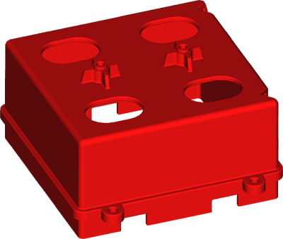
The Power Connector Circuit

The new battery box takes 8 AA batteries. I was hoping that all the batteries would be used for every thing, but on examination, all 8 = 12 volt are used to supply power to the logic circuits, but it still only uses 4 of the 8 batteries = 6 volt to power the drive motors. There is a socket for the remaining 4. I assume these are to power something else I have not installed yet.
12 volts was too much for the Driver Board, so a Fix was supplied to reduce 12 volts down to 8 volts.

Problem is the new battery box is higher than the old one and has a circuit board attached to the top of it. Because the new controller board I made reaches over old battery box, I have had to raise every thing.
I have printed 2 plastic supports to raise every thing on my 3D printer.

Each support is made in 2 parts so that I can keep every thing aligned.
The top part is made to take to take brass grommets for the threaded spacers to screw into.
This shows the new battery box in front of the parts raised.

A closer look at the supports.

And with the controller board on

Here is the layout of the finished board.


Resistor R16 does not need fitting.
The potentiometer for adjusting the frequency of the sonar transmitters ends up under the Infrared TX and RX dome. So don't fit the dome until this has been done.
When the dome is fitted, it covers the reset button on the Arduino Nano, so I fitted a remote reset button.

I have had to flip the buzzer up side down under the speaker mounted on the dome unit.
(This will not need to be done if you are using the old battery case and have not raised the boards above the new one.)
(By the way, the blue plastic piece is something I made to fix the dome, as the 2 delicate little tags that hold it, have broken off.)
The first thing to do once the Controller Board is fitted, is to adjust the frequency of the Sonar TX Driver.
This would be quite easy to do if I had an Oscilloscope, but I don't have one.
So I am going to use my Arduino ONO to set it up.
Care needs to be taken when using an Arduino to probe values on a circuit.
When a pin has been set as an input, the voltage in must not be more than 5 volt and must not be a negative voltage. Either case could damage the Arduino.
The Circuit for my Arduino ONO is a simple one, just 2 wires.

The Sketch is as follows:
int myCounter = 0;
void setup()
{
Serial.begin(115200);
pinMode(A0,
INPUT);
}void loop()
{
myCounter++;
if (myCounter >= 1000) {// After 1000 loops, freeze the output for 5 seconds
delay(5000);
myCounter = 0;
}
Serial.println(analogRead(A0));
}
Tims_Cybot_Sonar.ino
With this Sketch uploaded I use the Tool: Serial plotter.

Before connecting this to the output from one of the Sonar RX cables, the Sonar TX Driver needs turning on.
To do this a small sketch needs uploading to the New Cybot Controller (Arduino NANO).
It needs to be turned on because I made the circuit that way to save power when not using the Sonar. Also it leaves an option to write some code to turn it into a rangefinder. (this may not be possible due to other libraries altering timers)
The Sketch to turn the Sonar Driver on is very simple, all it needs to do is switch pin 12 on.
void setup()
{
pinMode(12, OUTPUT);
digitalWrite(12, HIGH);
}
void loop()
{
}

It consists of a 555 Timer circuit and an Inverter(x6) 4069.
As the frequency that the timer is to be set is quite high, (40kHz) and components are manufactured to a tolerance. I have included a potentiometer in the circuit so it can be calibrated to match the Ultrasonic Transmitters.
The inverter is used to create bridged configuration to give 10v difference between pins. (This is still a bit on the low side for these Transmitters, but is adequate for them to work. It just means things need to be close to get good results.) I found the max range I am able to get good results is 200mm, if you check issue 43, this is what it had with there processor.
At this time the New Controller Board (Arduino NANO) can be powered from the USB cable, there is no need to switch on the batteries.
So 2 USB cables are going to be connected to the computer, one for the New Controller Board (Arduino NANO) and one for the Arduino ONO.
An obstacle needs to be placed in front of the Sonar RX and Sonar TX used for calibration, if in doubt place an obstruction in front of the left and right Sonar.

Open the Arduino IDE and configure it to the Arduino ONO.
Without any of the cables from the Arduino ONO connected to the New Controller Board.
In the Arduino IDE (ver. 1.8.3) select from Tools, Serial Plotter.
NOTE! Serial speed is:115200, make sure this set when the Serial plotter is open.(bottom right)
This is what should be displayed:

This is noise, I think this is a very nice tool, but, it would be nice if the vertical scale could be set.
The vertical scale adjusts its self automatically depending on the average value being received.
So the important thing to watch here is the values on the left, the shape of the plot is not relevant at the moment.
In the sketch I have created a delay every 1000 loops, and the delay is for 5
seconds.
Remember this when adjusting the potentiometer, while the screen is stationary, it is not taking any readings, so adjust it a little bit at a time and wait for the result.
The values on the left are 5 volts divided by 1024, so each unit equals 0.0048828125 volt.
So the difference you see in those spikes are about 0.03 volt.
Not a lot, as I say, the Serial Plotter automatically adjusts the vertical scale.
The next step is to connect the 2 cables from the Arduino ONO to the New Controller Board.
GND from the Arduino ONO goes to GND on the Controller board.
A0 from the Arduino ONO goes to one of the cables soldered to the Sonar I/O board.
You can use the 2nd pin of the I2C Raiser for GND (Take care to get the right one)
Connect directly to one of the pins in the plug from the Sonar I/O board.

With the cables connected and the potentiometer set at centre.
The plot should look like the following:

Take note of the values on the left, the change between the spikes is between 495 and 540.
This works out at about 0.2 volt Amplitude.
Adjust the potentiometer until the number at the top on the left changes to 1000 or more, and the number at the bottom on the left changes to 0.

Take note of the values on the left, the change between the spikes is between 495 and 540.
This works out at about 0.2 volt Amplitude.
Adjust the potentiometer until the number at the top on the left changes to 1000 or more, and the number at the bottom on the left changes to 0.

Also while it shows minimum of 0 and maximum of 1000, try to get the spikes as large as possible.
Here the difference between the spikes is between 0 and 775.
This works out at about 3.7 volt Amplitude. (this is high enough for a 5 volt logic true value)
Now remove the obstructions placed in front of the sonar sensors and the plot should change to something like the following:

Here the spikes are between the values of 460 and 580.
This works out at about 0.6 volt Amplitude. (this is low enough for a 5 volt logic false value)
When I write the code for the sonar, I won't be using actual voltage from the sensor I will be using the Amplitude. (the strength of the signal)
Once this has been done the Infrared TX and RX dome can be fitted.
Make sure the cables from the Sonar and Light board are plugged also the cables for the remote reset switch are plugged in. As these end up under the dome.
Make sure the wires from the Sonar and Light board are the right way around.
Viewing Cybot from the rear, pins on the left are left sensors, pins on the right are right sensors.
Cables I used for the Sonar board where Red-Left, Black-Right.
Cables I used for the Light board where Black-Left, White-Right.

My Converted Cybot

Time to Write some code to control it.
There will be an application to make, so that I can control it from my computer via Bluetooth.

Time to Write some code to control it.
There will be an application to make, so that I can control it from my computer via Bluetooth.

This require a Bluetooth Dongle for the computer if it does not have Bluetooth
built in.


When attaching this device to the controller board, make sure that it is
plugged in the right way around.
Although the Power pins can take 5 volts, the DATA Pins CAN NOT.
I also want to control it from an Infrared remote.

Although the Power pins can take 5 volts, the DATA Pins CAN NOT.
I also want to control it from an Infrared remote.

I am using a cheep
Remote
I got with my Arduino kit.
The Library for my Arduino Sketch is this one: Arduino IRremote
If the Infrared Remote is not the same as the one shown, my firmware will need
to be modified to use the correct codes.The Library for my Arduino Sketch is this one: Arduino IRremote
Firmware also need to be written so that the New Controller board (Arduino NANO) knows what to do.
Before I write the software, I need to decide a protocol (a command language)
I am going to use.
My previous projects like XY Plotter, 3D Printer and a 6 Axis Robot Arm. Have
used modified versions of G-Code.
So I have decided to use something similar.
G-Code is mainly controlling the position of something in and XYZ coordinate
environment.
The control of the Cybot is more of a Telemetry environment.
So I am going to call my Protocol, T-Code. (my name is Tim as well, hehe.)
Each command has a Primary Command and Command Values.
e.g. "T01 A45"
This would tell Cybot to use Function T01 with Variable A45.
The current protocol I have come up with so far, is as follows:
Telemetry and Task
T00 Get all Telemetry info.
T01 Set Front Steering A=value
T02 Set Rear Steering A=value
Motor Control and Mode
M00 Turn Motors Off, N=motor selection
M01 Turn Motors On, N=motor selection
M02 Set Speed, S=value
M03 Mode, X=mode selection
Camera Control
C00 Pan Camera, A=value
C01 Tilt Camera, A=value
Device Control
D00 Device Off, I=Device ID.
D01 Device On, I=Device ID.
I will be using this protocol later when I write the program to communicate with the Cybot from my computer via Bluetooth.
Now lets jump in the deep end.
The Link for the Firmware is at the top of this Blog.
(I have placed the link at the top to make it easy for me to keep the link updated with the latest version.)
Upload to the New Controller Board (Arduino NANO).
The current Sketch has the following Modes:
00 -- (0000) Command Mode
01 -- (1000) Light Seek (Fast)
02 -- (0100) Light Seek (Speed Controlled)
03 -- (1100) Avoid Objects (Fast)
04 -- (0010) Avoid Objects (Speed Controlled)
05 -- (1010) Line follow (Fast)
06 -- (0110) Line follow (Speed Controlled)
07 -- (1110) Follow objects (Fast)
08 -- (0001) Follow objects (Speed Controlled)
09 -- (1001) Infrared Control (Button Hold)
10 -- (0101) Infrared Control (Button Press)
If setting Mode with the DIP Switches, press the reset button on the Arduino NANO for the setting to take effect.
I will be changing the modes as I progress with the coding.
The firmware is still work in progress.
So far I have done screenshots of Arduino IDE, this is because I needed to use the Serial Plotter Tool.
I do other programs for the PC and web, for which I use MS Visual Studio. Every thing I do is as a hobbyist and for personal use.
My current Version is:
Microsoft Visual Studio Community 2017.
It is a very helpful IDE so I use this to do Sketches for my Arduino projects.
To enable it to do this I have added an Extension for the Arduino series called:
Arduino for visual studio.Future Screenshots will be from Visual Studio, but the principles will be the same.
Time to set up the Bluetooth Device.
As I mentioned before, it is important that the device is connected the correct way around.

The DATA connections can only handle 3.3 volt, I have added a bi-directional logic voltage conversion circuit to the Controller Board to accommodate this.

The 2 MOSFET's take care of this.
The default UART BAUD rate for the Bluetooth device when received is usually 9600.
I want to increase this speed. As I am using Soft Serial to communicate with the device, there is a limit to the speed that can be used, this is: 57600bps.I will be setting mine to: 38400. I may increase this at a later date.
To do this an "AT" command can be sent using the Serial Monitor.
I have based configuring and setting up of my Bluetooth Device on this document: Bluetooth Modules.
There are many Bluetooth devices (Chinese Clones) on the market. Not all are the same, there are various different chips used, chips that have been designed for a specific task. So finding the right manual can be difficult.
There are several ways to set up the Bluetooth Device, I am going to do it the easy way.
The first thing needed is a small Sketch so I can communicate with the device.
#include <SoftwareSerial.h>// software serial.
#define BT_RX A2 // Bluetooth RX to Arduino TX.
#define BT_TX A3 // Bluetooth TX to Arduino RX.
SoftwareSerial BTS(BT_TX, BT_RX); // (Arduino RX, Arduino TX).
void setup(){
Serial.begin(115200);
BTS.begin(38400);//9600 default,38400
}
void loop(){
char BT_Data = 0;
if (Serial.available()) {
BTS.write(Serial.read());
}
delayMicroseconds(1000);
if (BTS.available()) {
BT_Data = BTS.read();
delayMicroseconds(1000);
Serial.write(BT_Data);
}
delayMicroseconds(1000);
}
void loop(){
char BT_Data = 0;
if (Serial.available()) {
BTS.write(Serial.read());
}
delayMicroseconds(1000);
if (BTS.available()) {
BT_Data = BTS.read();
delayMicroseconds(1000);
Serial.write(BT_Data);
}
delayMicroseconds(1000);
}
Open your preferred IDE and load the above Sketch.
Once loaded, edit the BAUD rate for the Software Serial. It needs changing to 9600, the default speed of the Bluetooth Device.

Once Changed to 9600 upload the Sketch to the New Controller Board, open the Serial Monitor and set the speed of the Serial Monitor to: 115200. (This is what I have set the USB Serial to)
The Sketch reads what is sent from the Serial Monitor via the USB and sends it to the Bluetooth Device via the Software Serial.
The Sketch reads any DATA from the Bluetooth Device via the Software Serial and sends it to the Serial Monitor via USB.
NOTE! Some Bluetooth devices require the characters "?" and "=" in the command, some don't. depends on the chip and firmware version.
So try the commands with and without them, to see which gives a reply.
The reply could be just OK or it may confirm what was requested.
First thing that may be changed, is it's name.
This is done with the following command: AT+NAME=<name>
This is done with the following command: AT+NAME=<name>
<name> = what ever the device is to be called.
e.g. I sent the command: AT+NAME=Tim's Cybot (could be: AT+NAMETim's Cybot)

After sending, I got a conformation OK (could return: NAME=Tim's Cybot)

After sending, I got a conformation OK (could return: NAME=Tim's Cybot)
I want to change the baud to 38400, you cant just change the baud on it's own on the module I have. It's changed with the UART settings.So the command to do this is: AT+UART=38400,0,0
This sets the UART: baud = 38400, number of stop bits = 1 and Parity = None.
Don't Expect a reply after sending this command, the baud has just been changed to 38400 and the Serial software is set to 9600.
Close the Serial Monitor.
Edit the Software Serial Speed back to: 38400.
In the Serial Monitor send the following codes:
AT+NAME? (This should return the new name)
AT+UART? (This should return the UART settings)

You should get the results shown in the Serial Monitor like the ones above.
That's it for the Bluetooth Device, no more needs to be done with it.
(Well there is, there's the Radio BAUD but I'm not doing that until I have a spare Bluetooth module, the current one I have is on a board with only 4 pins, it will involve adding another wire to set it manually to command mode.)
The reason I used a Sketch to set up the device, is because to be able to do it from the PC after pairing, the CMD Pin 34 would need setting Logic High. As the device I have is only 4 pin, I didn't want to add another pin for a one time setup. (At this time)
The next thing to do is pair up the Bluetooth Device with the computer.
1. Plug in the Bluetooth Dongle into the computer.(if the computer dose not have Bluetooth)
2. Plug in a USB cable into the New Controller Board to supply power.(no need to use the batteries)
3. Pair Devices:
I have Windows 10
Settings

Devices

Add Bluetooth or other device

Bluetooth

After a short time windows should pick up the Bluetooth Device connected to the New Controller Board.
The name of the Bluetooth Device will be different, I have changed the name of mine.


Click Done and close settings window.
Now that the Bluetooth Device is paired with the computer, it is possible to communicate with it direct.
If unsure which COM Port the Bluetooth Device is Paired on, open device manager to get an idea
which it is:

It's either COM10 or COM11 for me.
(It's actually both in a way but I 'm not going into that at the moment)
Install and open my Application: Tim's ROV Controller.
The Link for the Application is at the top of this Blog.
(I have placed the link at the top to make it easy for me to keep the link updated with the latest version.)

Turn on the power to the Cybot.
Set the COM Port to the correct Port.
Set the BAUD rate to whatever. (This BAUD has nothing to do with Arduino)*
Click Connect.
*when connected I think there are actually 3 BAUD speeds used:
Arduino < BAUD > Bluetooth device on controller Board.
Bluetooth device on controller Board < BAUD > Bluetooth device on PC
Bluetooth device on PC < BAUD > PC.
If it connects successfully, the connection text should turn green.
Tick the box: Link Steering. The Cybot has only 2 wheels.
Sliders for Devices 1 and 2, set the sensitivity of these two devices.
Type Antenna in the box for Device 3. This is what these buttons for this device control.
Type Buzzer in the box for Device 4. The ON button for Device 4, sounds the Buzzer.
Other Devices have not yet been added.
The Mode dropdown selection box will set the Cybot in the chosen mode.
Setting up the Infrared Control
To do this I have a basic Sketch:
#include <IRremote.h>
long receivedValue = 0;// Value received from IR
#define IR_RX 2
#define IR_TX 3// This definition is not used, pin 3 is used by the library's > IRsend
#define LED_ANTENNA 4
IRsend irsend; //Send Infrared. (IR library sets pin 3 for this)
IRrecv irrecv(IR_RX, LED_ANTENNA); // Receive Infrared. (IR library sets pin mode of IR_RX LED_ANTENNA pins)
decode_results results;
void setup(){
Serial.begin(115200);
irrecv.enableIRIn(); // Start the receiver
irrecv.blink13(1); // Enable Infrared Receive acknowledgement (blink) on the antenna.
//No need to setup pin modes, library for IR does this
}
void loop() {
IR_Receive();
}
void IR_Receive() {
if (irrecv.decode(&results)) {
Serial.print("HEX Value = ");
Serial.print(results.value, HEX);
Serial.print(" Numeric Value = ");
Serial.println(results.value);
receivedValue = results.value;
irrecv.resume(); // Receive the next value
}
}
This is the part of the Circuit on the new Controller Board that takes care of
the interface with the IR TX & RX in the dome on top of Cybot.

Upload the sketch.
Open the Serial Monitor and set the speed to 115200.
Point the IR Remote at the dome on top of Cybot and press the keys, each in turn.
The result from each key press should show in the Serial Monitor.

The results should look some thing like the ones above.
When a key is pressed a Unique Number is transmitted followed by HEX "FFFFFFFF"
If the key is held, HEX "FFFFFFFF" is repeated after the transition of the Unique Number.
I have found some little quirks with this Library and after running the library with the rest of my code I have slightly different results. I think it's due to some timing differences. I'm not going to try and fix the Library.
These are the results from the IR Remote when run from the Main Sketch. (I added Type to help with debugging)

I think the Type with a negative number are corrupt.
Each Unique Number Need to be mapped to it's relevant Key.

From this I made a new map I am going to use to control the Cybot.


And attached it to the IR Remote Control

Made a Pan and Tilt Platform to mount a Camera.

To control the Pan and Tilt Platform, I have added a
PCA9685 16 Channel 12-bit PWM Servo motor Driver I2C Module

This module is controlled from the
I2C
bus, so no more pins are required from the Arduino NANO.
To make things nice and tidy, I removed the header pins it came with and added
vertical header pins at both ends pointing down.
This is so I can plug it into sockets on a new board I have made to fit above
the Main Controller Board.

Also on the board I have added a header to supply power to the servos.
The 16xPWM board has a regulator that can accept 6 volt so I will tap into the power used to drive the motors.

Top PCB Circuit
I have a VL53L0X

So I decided to attach it to the Pan/Tilt Platform (I'll make a proper bracket when I get the Camera )
I did this so I could make a Range Finder.

So I have modified my Controller program to Scan the Area.

Still waiting for the camera I have ordered.
Been working on the Controller, have done some updates to the rangefinder.

I found it a little difficult to control my Cybot as it was, so I have added a simpler control for movement.
Been working on the Controller, have done some updates to the rangefinder.

I found it a little difficult to control my Cybot as it was, so I have added a simpler control for movement.
I have found this arrangement much better and I think I will change the
Infrared Remote buttons to the same configuration.
Normal alkaline batteries don't last too long, I want to try and increase the length of time I can use them.
As it stands only 4 of the batteries power the motors, so they are getting a 6 volt supply.
As these batteries discharge and fall below this voltage, the power loss is noticeable.
As I am not interested in football and am not using my Cybot with others, I will not be fitting the arms that where made to go on the front. (Not doing Cyball) This means the socket "TO-UC6" on the Power Connector will not be used.
I checked the stall amperage of a motor and found it to be about 1 amp.
Doing a search on the MC7806CT voltage regulator that is on the Power Connector, states it can handle excess of 1 ampere and handle a peek output of 2.2A
I have decided to modify the Power Connector to supply power to the motors through the MC7806CT on the Power Connector.
Doing this will use all the batteries, which will be a 12 volt supply reduced to 6 volts.
So hopefully the reduction in voltage from the batteries will not be noticed until the power in the batteries are a lot lower, increasing the time I can use them.
This is not too hard, to do it involves:
Removing Diode D2.
Removing the soldered link next to C1.
Add a wire link from the Input of the MC7806CT to the 12 volt terminal.
I also decided to move the fuse, (I am putting the fuse on the logic power) this involves:
Cutting 2 copper tracers.
add an other wire link.
The best way to show what I did, is in the following photos:


The new Circuit


The alteration on the power supply was an improvement, the batteries did last longer.
I felt I was still having power issues, noticeable when using the Infrared Remote. The power surge from the motors interfered with the Infrared Timing, giving errors when receiving.
To over come this I decided to get some rechargeable batteries.
Before the addition and modification to the Power Connector (power regulator), it was not possible to use rechargeable batteries.
Rechargeable batteries are only 1.2 volt so the 4 used for the motors would have only supplied 4.8 volts. (basically this voltage is the discharged state of the Alkaline batteries)
The current Battery Box (upgraded one) will take 8 x AA Batteries.
So replacing Long-life Alkaline with Standard NiMh Rechargeable Batteries is not a good option.
Long-life Alkaline: 8 x 1.5v (1.2v Discharge voltage) with 1500mAh = 14.4Wh.
NiMh Rechargeable: 8 x 1.2v with 800mAh = 7.68Wh.
Although I will be able to keep recharging them, they only last half as long before needing a recharge.
I also want to increase the time I can use my Cybot, before a recharge is needed.
So I decided to look for some Lithium Polymer (Li-Po) Battery
I found these on Ebay:

6 x 3.7v with 1200mAh = 26.64Wh.
Nearly twice that of the Alkaline Batteries.
Also the physical volume of these batteries when stacked together equals approximately 57mm x 58mm x 31mm.
This works out about the same size of the current Battery Box. So I will be able to place them in the same place as the current batteries.
Rather than modify the existing Battery Box to fit the batteries, I made a new one on my 3D Printer.
New_Battery_Box.stl
To be able to recharge the batteries I need to keep the original plugs on them. (make no modification to the battery leads)
So to connect the batteries a connector strip needs to be made.
 What you see above is the plugs from the batteries connected to bare pins.
There is no actual sockets. I needed to keep a low profile with this board so
that it fits inside the battery compartment. I just soldered the pins to the
PCB.
What you see above is the plugs from the batteries connected to bare pins.
There is no actual sockets. I needed to keep a low profile with this board so
that it fits inside the battery compartment. I just soldered the pins to the
PCB.
Rather than send 6 x 3.7 = 22.2 volt into the regulator, I have split the batteries into 2 banks of 3 x 3.7 = 11.1 volt.
The circuit of the Battery Connector Strip looks like this viewed from the underneath:

New Battery connector Strip
New Battery Box with batteries and Connector Strip:

Front View Fitted:

Viewed from underneath:


I Had to remove the ridges from the inside of the battery lid.
Charging doesn't take long.

The charger is very small, so charging can be done with the batteries in situate.
I have placed a ribbon behind the batteries to aid removal should I want to do so.
After the Battery Upgrade, I tried the Infrared Control and the Line Follow mode again.
There was a great improvement.
The increase of power from the new batteries was very noticeable.
Although there was an improvement with the Infrared control there was still a noticeable bug in the system. I feel it's due to the Infrared code's us of the interrupt.
As my Cybot has Bluetooth, I have decided to make an application to control my Cybot from my Phone.
 I have based the application on the latest layout of my PC application.
Here I have tried to show the remote application in use.
With the Infrared receiver turned off, the control is much more responsive.
Nearly twice that of the Alkaline Batteries.
Also the physical volume of these batteries when stacked together equals approximately 57mm x 58mm x 31mm.
This works out about the same size of the current Battery Box. So I will be able to place them in the same place as the current batteries.
Rather than modify the existing Battery Box to fit the batteries, I made a new one on my 3D Printer.

New_Battery_Box.stl
To be able to recharge the batteries I need to keep the original plugs on them. (make no modification to the battery leads)
So to connect the batteries a connector strip needs to be made.

Rather than send 6 x 3.7 = 22.2 volt into the regulator, I have split the batteries into 2 banks of 3 x 3.7 = 11.1 volt.
The circuit of the Battery Connector Strip looks like this viewed from the underneath:

New Battery connector Strip
New Battery Box with batteries and Connector Strip:

Front View Fitted:

Viewed from underneath:


I Had to remove the ridges from the inside of the battery lid.
Charging doesn't take long.

The charger is very small, so charging can be done with the batteries in situate.
I have placed a ribbon behind the batteries to aid removal should I want to do so.
After the Battery Upgrade, I tried the Infrared Control and the Line Follow mode again.
There was a great improvement.
The increase of power from the new batteries was very noticeable.
Although there was an improvement with the Infrared control there was still a noticeable bug in the system. I feel it's due to the Infrared code's us of the interrupt.
As my Cybot has Bluetooth, I have decided to make an application to control my Cybot from my Phone.

With the Infrared receiver turned off, the control is much more responsive.
Time for a break (last edit May 2018)
If I get feedback and requests, I will go further into how the firmware works.
Also show how to make you own application in Visual Studio, if you don't want
to use my application.
I will keep editing this, as the project progresses and i get the incentive to write what i have done..
Thank you Mathijs, for leaving a comment.
ReplyDeleteI noticed you streamed a vid of your 3D printer. You may be interested what i have done with mine.
http://3dprintermods.blogspot.co.uk/2017/08/tims-modifications-to-a8-3d-printer-i.html
Great project. I might have to get my Cybot out and have a go, what software do you use to create the app?
ReplyDeleteHi, I did mention what I use in the blog.
DeleteI use MS Visual Studio Community 2017.
You didn't say which app?
I use VS for the android and the PC app.
I have added an Extension for the Arduino called: Arduino for visual studio.
If you put away your Cybot for the same reason I did back in it's day.
That is: I had issues with the remote controller not working.
I have done another post to this blog, to build an Arduino remote.
https://tims-arduino-cybot.blogspot.com/2018/06/tims-cybot-arduino-nano-remote-control.html
You may want to try that first, before converting the Cybot.
The remote also works with Tom.
Let me know how you get on.
Or if you need help.
Great project ! Im removing the dust from my Cybot after seeing this ! Thank you for your tutorials. Best regards !
ReplyDeleteThank you for leaving a comment.
DeleteIf your Cybot got, shelved for the same reason mine did, hope you read the infrared controller and battery replacement posts.
https://tims-arduino-cybot.blogspot.com/2018/06/tims-cybot-arduino-nano-remote-control.html
https://tims-arduino-cybot.blogspot.com/2019/09/converting-cybot-to-run-on-37-volt.html
I have more than one Cybot, when I changed the batteries, it put extra life into those I left original.
Happy Cybot-ing.
Did you felt any difference using 4x3.7 lipos instead of 6x ?
DeleteOh yes, much more responsive, sensors work better and longer play time.
DeleteThis video is it running on them:
https://www.youtube.com/watch?v=s-m6apRvCIo&feature=emb_logo
ReplyDeleteAwesome article, it was exceptionally helpful! I simply began in this and I'm becoming more acquainted with it better! Cheers, keep doing awesome!
edi diodes
Hey Tim, fantastic guide. I'm trying to accomplish converting our cybot over to using Arduino. When I got the point about "Controller Circuit R04(single sided)If you get the board made out, I have done a version using double side copper. (if you have it made out, you could change it to use SMD's to reduce the size.)
ReplyDeleteController Circuit (double sided)
Done some manual changes to my original board. I will do a double sided version when I have finished editing it.
During the writing of the firmware I have had to make some Arduino pin changes to make everything work with each other."
Can you clarify what manual changes you made and is the link to the Controller Circuit R04(single sided) the working version?
We're not equipped to make the boards ourselves so will be sending off the files to get them made.
Thanks
Lee